I am probably missing something simple, but I cannot upload the Arduino blink skech to an amb82-mini. I am using a clean, updated install of Ubuntu on a Celeron platform. The board appears to connect at ttyS4, with settings Erase then Upload, Auto Flash Enabled, Standard Lib Disabled, Upload Speed 2000000. The sketch will compile, but then it fails to connect, error messages including:
Ping fail
NOR flashloader loading fail
Uart boot fail
Upload fail
.ping fail
I still cannot enter download mode with the AMB82-Mini. I am doing the following:
Plug Board in using microusb (right side connection near red led)
- All leds (RG&B) flash quickly and then stay lit
Open Arduino Blink sketch & Arduino Serial Monitor (blank)
Press and hold Uart Download button (left side button near blue led)
Press and release Reset Button (right side button near red led)
- The green led turns off, the red and blue leds stay on
Release Uart Download button
- Nothing shows on the Serial Monitor
- Upload fails
Pressing Reset again causes the blue & green leds to flash quickly (red stays on) and then all leds stay on
Please help. I have tried 3 different boards and many operating systems (Ubuntu, Debian, Kali, Raspbian, Windows 10 & 11) without success. I would like to be able to use this board in my current project, but it seems I may need to use something else (esp32?) since I cannot get this to work.
Also, I do not have access to social media in my current work environment, so I appreciate your help using the forum.
Thanks for providing more details regarding your questions.
After step 2 , you can follow the video instruction here to enter Download Mode on AMB82.
After entering the UART Download mode, you should be able to see the log in your serial monitor indicating your board is able to receive an uploaded image:
Alternatively, you can try with another USB cable to prevent connectivity issues.
If you are still not able to enter the download mode after trying the above methods, please provide the log message after step 1 here for issue assessment.
, friends, I hope you can help me, I also have this problem, I bought 02 AMB82 board, and I have the same problem, I cannot load any code and carry out the uart steps, it also recognizes the CH340 cable and the port, when it comes to perform the download also follow the steps of the buttons and I get this image I hope you can help me, thank you very much
Hi. I had the same problem as in above post with upload fail…ping retry fail…with new board today and blink test sketch. I made many tries on the recommended use of the boot and reset button sequence with no success. Finally I just held down the boot button while it uploaded, …dot sequence. I did nothing with the reset button and it booted up…upload success. Maybe change instructions if this is universal?
There is no change in instructions. Can you double check one thing, when you go into serial monitor, press the two buttons at the side of AMB82-mini, screenshot what you see there.
Hi Again. After a few more upload attempts after making sketch changes, the single button method no longer worked either; I just get variations of this ping fail, as others have:
To everyone experiencing the communication issue above - after hours of fighting with the board, I’ve come to the following result: First, the sequence to enter upload mode is pressing Reset (the button next to the red LED), then press Download, then release Reset, and then release Download. Second, the cable is very important; after replacing several cables, I found one that establishes good communication and manages to upload the program without errors. I don’t know why this is, but I had a similar issue with ESP32, probably due to the driver; maybe Realtek should provide a verified cable with the kit. Good luck to all enthusiasts!
I was facing the same issue. I fixed it by downloading the right USB driver from CH341SER.ZIP - NanjingQinhengMicroelectronics and confirming if the device shows in device manager (previously it did not). Rest, followed the steps as discussed by @dakamaster. Hope this helps!
I am again experiencing upload problem. I have a number of working boards so am familiar with the upload process but a new one on first connection to PC has both LEDs, the blue and red lit all the time after power applied, not just when in upload mode. Hence doing the above button upload sequence makes no change. The PC recognizes the com port; I also tried other working USB cable. Deepseek suggests erasing possible corrupted flash, but can’t upload to erase. Finally DS suggestion of defective or mis-soldered NOR flash and only option is to replace board. Here is verbose:
Sketch uses 9580544 bytes (57%) of program storage space. Maximum is 16777216 bytes.
“C:\Users\Mel\AppData\Local\Arduino15\packages\realtek\tools\ameba_pro2_tools\1.4.5/image_windows.exe” “C:\Users\Mel\AppData\Local\Arduino15\packages\realtek\tools\ameba_pro2_tools\1.4.5” “COM3” “{board}” “Disable” “Enable” “2000000” “uartfwburn.exe” “Auto_Flash_Pro2_V3.3_win.exe” “0x60000” “0x460000” “0x530000”
Enter Flash Mode!
Start Erase Flash
Erasing.Create File Error
Sorry to hear your bad experience, the case is very rare. In my opinion, it is more sound like a HW failure. But lets do some testing to see how deep we can dig in.
First of all, this is a upload mode entering issue, we going to focus on, CH340 chip, buttons and related software.
Make use there is only the faulty board connect. And enter the upload mode.
if there is com port, has log “Download Image over UART“. means the CH340(uart to use chip) functions and entered the upload mode successfully
if there is has/no com port, with no log. means the log uart usb has some issues.
use correct baud rate to avoid any setting errors.
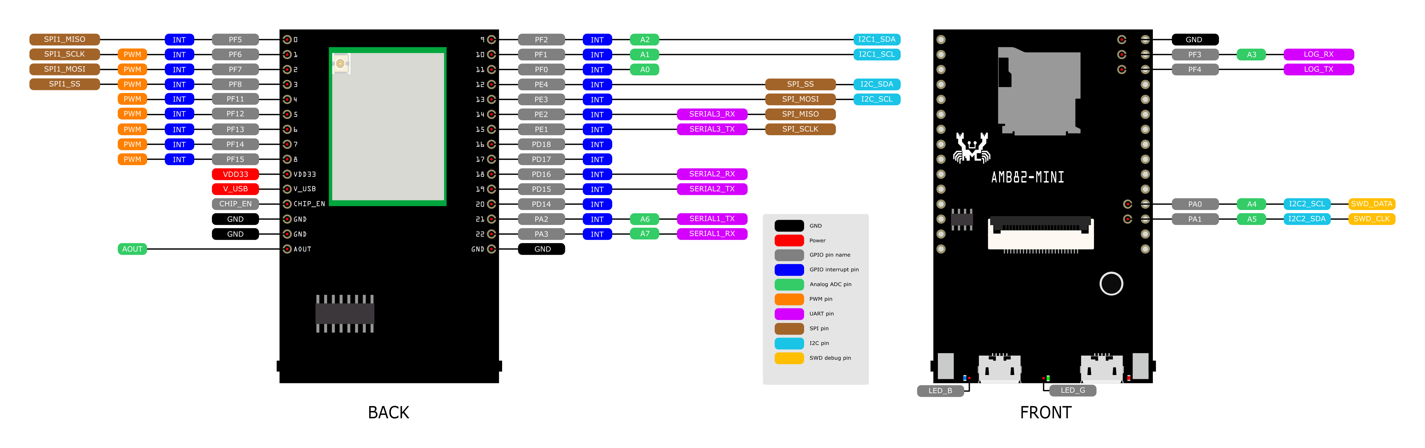
Try to connect an external UART to USB connector to see if there is log, AMB82-mini pinout
from the circuit, we know that 23 (PF9) and 24(PE6) are blue and green. it can be tested, by connect VDD33 to Pin23 and 24, touch and go see if the LED is light up.
for button, SEN_PWR_EN linked to upload mode button, CHIP_EN linked to Reset button.
reset button check, if there is no reset by button
the board should reset. if no, there will be more critical HW issue that suggested to replace this board.
upload mode button check, if you can not enter the upload mode
find the SEN_PWR_EN,
there is no pin out for SEN_PWR_EN, but we can find a pin at the wifi module, refer to bellow. Right bottom corner (the circel) is the antenna connector. Top from right, the second pin is the SEN_PWR_EN.
In short:
If the UART log is not visible, please use an external UART-to-USB adapter.
If the button can not enter upload mode, please try the SEN_PWR_EN method.
Thank you for your assistance. Last night I removed the Amb82 from the unpopulated PCB with pin headers I used for mounting and then found the board started to work, and would boot. I found using a microscope that a tiny solder fleck had shorted 2 pins near the boot button was the cause of the problem. All good now.
Mel


