Hello AmebaIoT community! This topic is specially created to help creators like yourself to realize your applications with camera sensor modules that are not officially supported by us yet. We hope that this will enable more people to exploit the powers of our AmebaPro2 boards to a far greater extent. This post will be continually improved upon based on the questions we receive from everyone, so please feel free to ask more questions here for us to help you!
[Hardware]
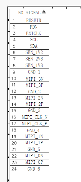
- Our AmebaPro2 boards use a specific set of 24-pin MIPI configuration as shown below. It is important that your camera sensor module follows the same pinout configuration or have an adapter to connect the module to these pins exactly. It supports only the 0.5mm pitch pins and the pins should be 1 to 24 from left to right as shown.
- The recommended length of the FPC/FFC cable(s) is to be within 100mm for a more reliable MIPI connection.

[Software]
-
Check the list of our officially supported camera sensor modules in
sensor.h. You can find the header file under{SDK}\project\realtek_amebapro2_v0_example\inc\sensor.h. If the sensor is available, simply edit the following lines then do a clean build of your program and try to see if it works. The application can only support up to a total of 9 different sensors; you may replace any existing sensors within the list instead of adding on to it.#define SENSOR_MAX 5 static const unsigned char sen_id[SENSOR_MAX] = { SENSOR_DUMMY, SENSOR_GC2053, SENSOR_GC4653, SENSOR_F37, SENSOR_SC2333 }; #define USE_SENSOR SENSOR_F37 static const char manual_iq[SENSOR_MAX][64] = { “iq”, “iq_gc2053”, “iq_gc4653”, “iq_f37”, “iq_sc2333”, }; -
If your module is not yet supported, you will need to create a driver for it first. There is a lot of information for this section so please refer to the linked documents for the exact steps.
- Download the Sensor Driver Tool that is compatible with the SDK version.
- Create the driver binary file by following the steps in Driver Guide.
- You may follow the IQ Tuning Guide to tweak the IQ settings to your preference.
- Put the driver and IQ binary files into
{SDK}\component\soc\8735b\fwlib\rtl8735b\lib\source\ram\video\voe_bin. - Update “sensor.h” and do a clean build of the program.
-
If your module is supported and yet you encounter errors such as
[VOE][sensor_start][998]Errsensor_start check sensor id error[VOE]i2c_master_err_callback ERR:23, tx_len: 0, rx_len: 0you will need to edit the sensor driver as well. This can be typically be resolved by simply switching the current I2C slave address to the secondary slave address as noted in the camera’s datasheet. The I2C address variable to be changed is theinfo->i2c.i2c_idwhich can be found in the driver’s{SENSORMODEL}_get_info(...). For example the GC2053 would be named asGC2053_get_info(uint32_t isp_id, struct rts_isp_sensor_info *info).
If your problem is still not resolved then you may wish to check your FPC/FFC cable connection or even the camera module’s hardware.
[Sensor Bring Up Process]
It is essential to at least have the datasheet from your vendor to even begin. You might also wish to have a reference driver or an initial configuration file too. Feel free to copy paste an existing driver folder and rename it accordingly, then use this to develop your drivers so that it is compatible with our SDK.
- Refer to your datasheet for the Power Up Sequence and Required Input Clock Frequency for this step. In the
{SENSORMODEL}_get_info(...), edit the power up sequence by controlling theSNR_PWDN_GPIO,SNR_RST_GPIOandSNR_HCLK. Below is an example of a power up sequence. One way to verify that the power up sequence is successful is either using an oscilloscope to check if I2C R/W are successful. Another way is to see if the driver even reaches the{SENSORMODEL}_check(...)function at all, this will either result in the “sensor id err” message or show that it is passed if you have this configured correctly.
i = 0;
set_power_item(&up->items[i++], SNR_PWDN_GPIO, GPIO_HIGH, 5000);
set_power_item(&up->items[i++], SNR_HCLK, CLK_24M, 2000);
set_power_item(&up->items[i++], SNR_PWDN_GPIO, GPIO_LOW, 3000);
set_power_item(&up->items[i++], SNR_RST_GPIO, GPIO_HIGH, 3000);
up->num = i;
-
Check the datasheet to find the registers that contain the CHIP ID of the camera module. Edit the
{SENSORMODEL}_check(...)function such that it can verify that the correct camera module is connected. Failure to pass this check will result in the camera being unable to run after starting up. Different camera modules may expect a permutation of 1/2 bytes of register address and data, so this step may require you to change theinfo->i2c.addr_lenandinfo->i2c.data_lenin the{SENSORMODEL}_get_info(...)function as well. -
Once the check is successful, you can try using the UART command
ATII=info,mipito check if you are able to receive any MIPI data at all. This step is usually determined by your register settings instatic struct rts_isp_i2c_reg g_{SENSORMODEL}_i2c_init_regs_asic[]. Ensure that your settings are correct and compatible with AMB82-Mini’s output capabilities. Then check that the HTS/VTS/PCLK/FPS settings matches that which is set in your registers. Common problems at this stage is incorrect PLL register timings for your camera module and insufficient blanking for the row/columns. -
Once you are able to stream through your camera module, it is likely that the ISP will require some calibration for exposure/gain/black levels. Refer to the datasheet again to find the registers responsible for these settings and tweak them until the camera output appears normal on stream. Once it is normal and you wish to further improve the color accuracy, you may wish to use our IQ tuning tool to adjust the image quality of your particular sensor. (in [software] 2.3)